BMWdiy.INFO
E39 SmarTire Ashtray Install
Prepared by VietSB
Modified 07.25.03
NOTE: Perform these steps at your own risk. All P/N's listed are a "best guess", so please double-check with your local dealer. These mods and repairs were performed on my US-spec 1997 540iA (11/96 prod date, M62 engine) but there is no guarantee they will work on other E39's. These instructions are provided for entertainment purposes only!
BACKGROUND: The reinforced sidewalls of ultra low-profile tires makes it difficult to determine if tire pressure is low, simply based on driving feedback. When it's noticeable, the chances are high for imminent damage to the tire or expensive rim. A simple "walk around the car" inspection before driving off is a good idea, but in the event of a road hazard, these wireless pressure monitoring systems are a great idea. In fact, some high performance vehicles are now including variations of these systems as standard safety equipment, especially for run-flat tires.
There's another type of system that uses the ABS sensors to gauge changing wheel circumferences which could indicate a loss in tire pressure. I believe the SmarTire system is more accurate since it measures and displays individual tire pressures, internal temperature, and even estimated temperature-compensated cold pressure. Because the ABS-type system works off of rotation deltas, it doesn't actually display the current tire pressure and if certain tires lose pressure at the same rate, the system might not notice. The SmarTire system has audible and visual alerts for when the pressure drops below user-selectable limits.
I chose the SmarTire system based on my research and purchased thru The Tire Rack which was convenient since they installed the sensors free in the wheels I was buying. I hear tire installations are more difficult since the sensors can easily sustain damage if the tire installer/uninstaller doesn't take the proper precautions. These warnings are noted in the SmarTire documentation.
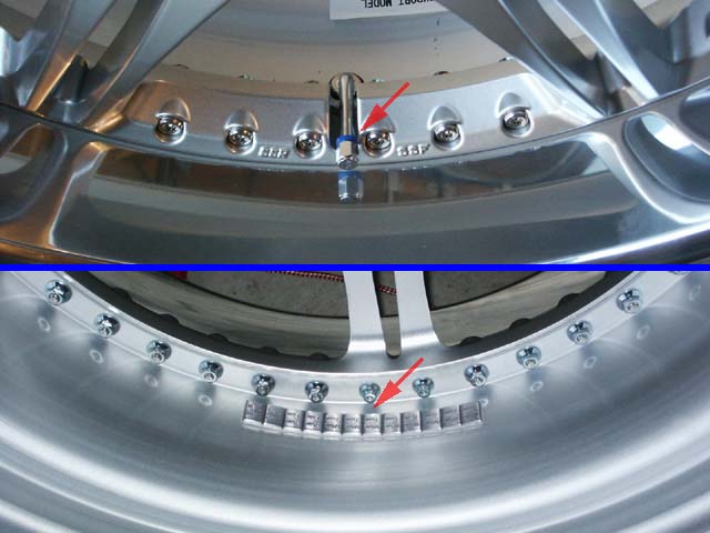
The system uses colored rings around the valve stems to indicate the position of the wheel on the vehicle for more accurate reporting. An installation drawback I noticed is the additional wheel weights necessary to offset the weight of the internal sensor. Again, the SmarTire documentation has important information regarding sensor placement and other items to keep in mind. Have a very good tire shop perform the balancing. No shimmy for me yet (knock on wood).
There are a myriad of ways to install this system. I preferred the stealth-look of planting the optional remote display into the front ashtray. Although this was the "slick" method, it also added many hours to my install time. Proceed accordingly based on your installation abilities and if in doubt, have a quality car electronics installer perform the work.
Required Parts:
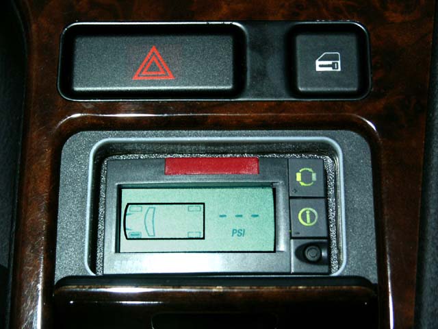
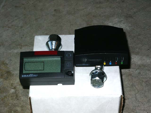
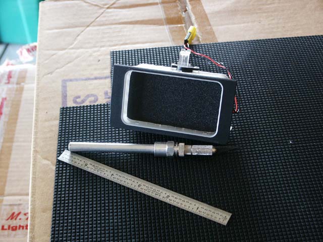
Remote display on the left, basic display on the right.
Additional Parts (if installing in ashtray):
- GC/Waldom WMLX-101 molex KK interconnection terminals and housings (~$2.70 at electronics parts stores)
- Radio Shack 274-1571 Size H, Coaxial DC power plug connector, 3.5mm O.D. x 1.3mm I.D. (~$2.50)
- Small length of wire
- Shrink tubing
- Thin black ABS plastic sheet
- Velcro or double-sided tape
Required Tools (if installing in ashtray):
- Precision flat-head screwdriver
- Phillips-head screwdriver
- Drill and assorted bits
- File or rasp
- Dremel and assorted bits
- Wire cutter/stripper
- Needle nose pliers
- Crimping pliers
- Soldering iron
- Heat gun
- Hot glue gun or equivalent
- X-Acto� knife
- Ruler
- Multi-meter
- Work light
- 3/8" Ratchet, extension, 13mm socket
1. Disconnect the negative lead of the battery if you are concerned with accidentally shorting anything electrical.
2. Pop out the gear selector trim, hazard, and door lock buttons to expose 3 screws to be removed. Unplug and remove the hazard and door lock buttons. Loosening the hazard button requires a precision flat-head screwdriver. Use care not to dent or mar the center console surface.
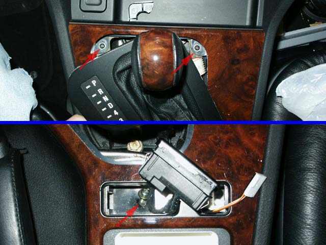
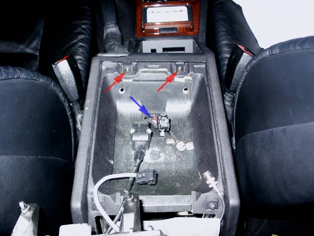
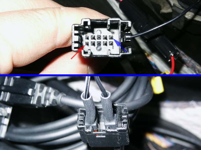
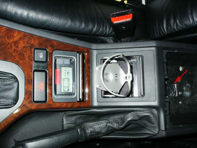
3. Follow the instructions on Agent99's page for removing the armrest. Remove the top two screws (see red arrows) to free the top section of the center console. Assuming you aren't using the cell phone wiring harness (see blue arrow), carefully push it down into the armrest. If you are using the factory cell phone, you'll need to modify the following wiring instructions and tap into the appropriate power and ground lines instead of connecting directly into the cell phone harness plug.
4. Double-check that all screws are removed and begin lifting the top panel. Unplug the ashtray light plug (see red arrow) and twist the white wiring harness located farther forward till it releases from the top panel (see blue arrow).
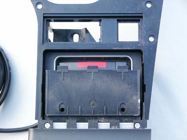
5. Remove black/chrome ashtray and ashtray carrier assembly from the top panel. Trim a piece of ABS plastic into a panel that fits nicely within the ashtray carrier. There are small white tabs in the assembly that should catch the panel and suspend it. Trim the panel so it isn't too difficult to remove.
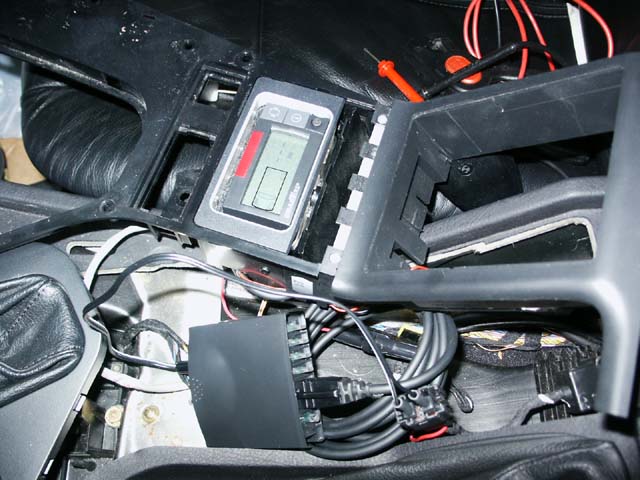
6. Prepare the remote display for installation by removing the rear screws and back plate to provide proper clearance. I also trimmed the indented edges off the rear of the faceplate to provide a better flush fit against the new trim panel. Only one screw can be reinstalled (see red arrow) so I carefully hot-glued the rest of the circuit board to the plastic edges.
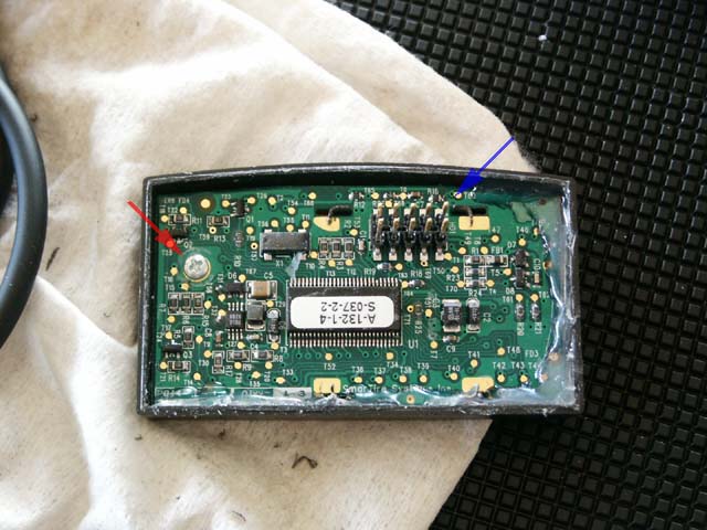
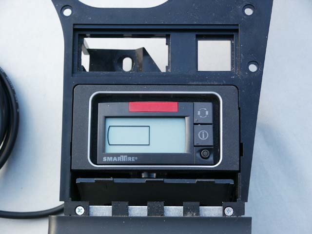
7. Drill a suitably-sized hole in the new trim panel to allow the harness contact pins on the back of the remote display (see blue arrow in above pic) to protrude thru the panel. Placement of the hole is very important as the display unit should be positioned properly (as per the picture at the top) when the pins are aligned thru the hole.
8. Unsnap the bottom piece off the ashtray carrier assembly and drill a suitably-sized hole towards the left front of the assembly (approximately 10'oclock as per the picture) to allow the 90-degree connector portion of the harness to fit thru.
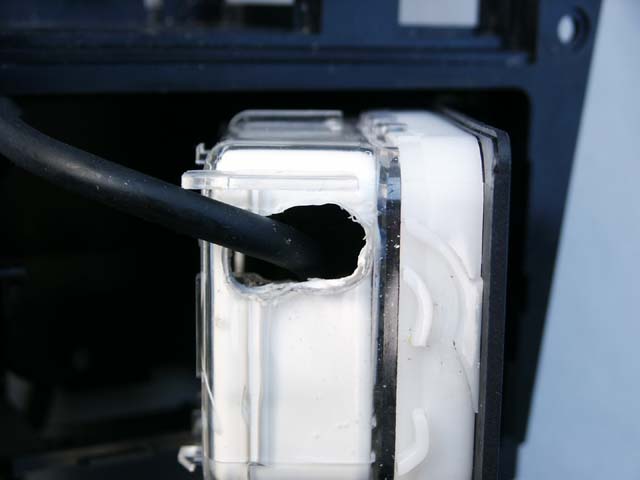
9. The outer portion of the carrier had a small wire-management tab that I trimmed off to make room for the larger cable. I used the hot glue gun to affix the 90-degree harness down into the ashtray carrier. After that, the new trim panel and remote display simply pushed down onto the wiring harness with the connector mating being all that was necessary to keep it in place.
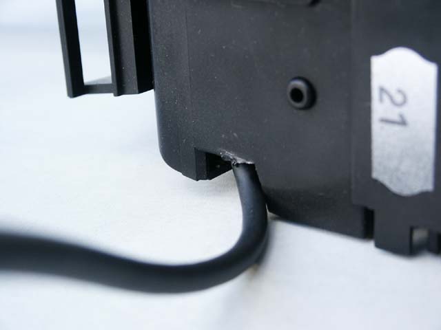
10. Reassemble the ashtray components and leave enough slack in the cable to allow for the smooth actuation of the ashtray carrier lifting mechanism. I didn't explain much detail for the last few steps, but that portion alone took over an hour. Most importantly, check to see the best exit path for the thick remote display cable. If you aren't careful, the cable will route outside of the assembly, but will offer too much friction so the assembly will no longer perform the smooth lift.
11. If connecting directly into the cell phone wiring plug:
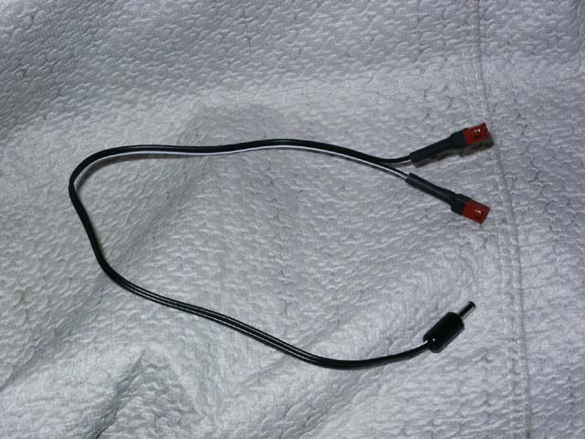
With the wiring parts listed above, build a harness similar to this one, with the center conductor in the DC power plug being the +12VDC connection and outer jacket being the ground connection. Check on your SmarTire unit to be sure this is the correct polarity. The molex connecters should only utilize one pin in each, leaving the 2nd pin empty.
12. Double-check on your car with a multi-meter!:
After checking for loose wires, reconnect your battery and verify that Pin #1 is switched +12VDC and Pin #10 is grounded. Your car's wiring could be different. Toggle your ignition on and off to the accessory click to verify Pin #1 is "switched" power. Plug the new molex ends into the cell phone harness, aligning the pin that is present into the corresponding +12VDC and ground pins. They should fit nicely and not be very loose.
13. After verifyng correct polarity on everything, attempt a connection using the basic and remote SmarTire displays.
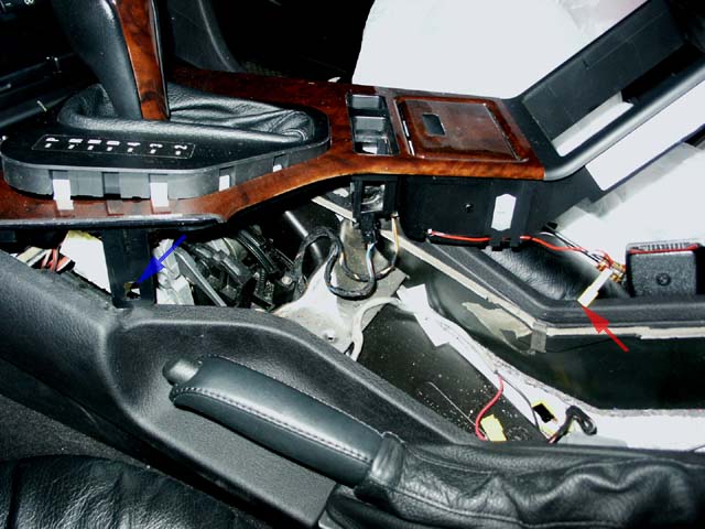
14. I hid the basic display below the armrest tray, next to the air duct (visible from the front) and used Velcro to attach it to a vertical metal bracket.
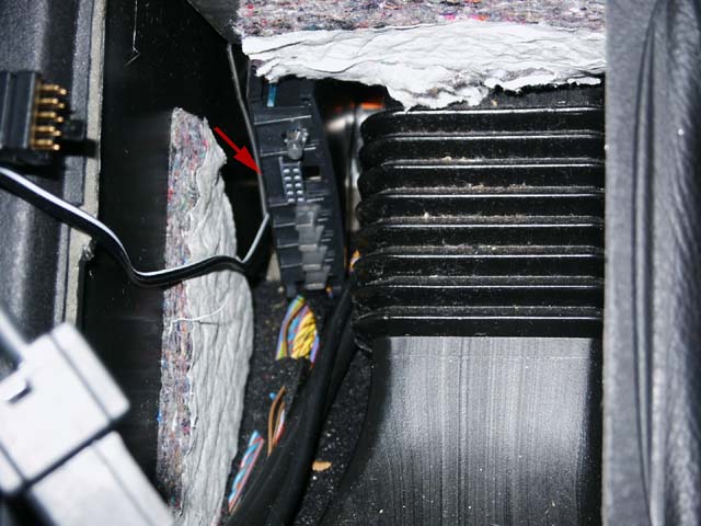
15. Hide the remaining coiled display harness below the armrest tray (see red arrow) and reassemble the center console and armrest.
16. Enjoy the security of knowing your tire pressure at any time!
|
Questions? Comments? E-mail me:
|
 . .
|
Click Here to return to the Main Menu.

Optimized for 800x600 or higher resolution.
Copyright © Midnight Designs, 2002-2003. All Rights Reserved. All
images and registered trademarks are used to benefit and without intent to
infringe on the holder. Contents Subject to Change Without Notice.